Creating a definition file
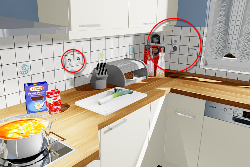
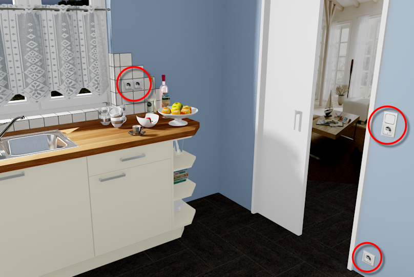
We would like to illustrate the individual steps that are necessary to create an installation symbol by means of a practical example, so that you can understand these steps better. To this we will first use the power socket with switch, to which we referred to in previous descriptions. We use the pictogram according DIN-VDE-Norm for a safety power socket with switch, as template for the 2D installation plan. For the perspective we additionally Addition (in Latin: addere) is one of four basic operations in arithmetic. In primary school and in common language it is the expression used for the adding of two or more numbers. use a picture of a white safety power socket.

First some groundwork has to be done and information has to be gathered, which must then be entered in the definition file, in order for the creation of the definition file to occur smoothly.
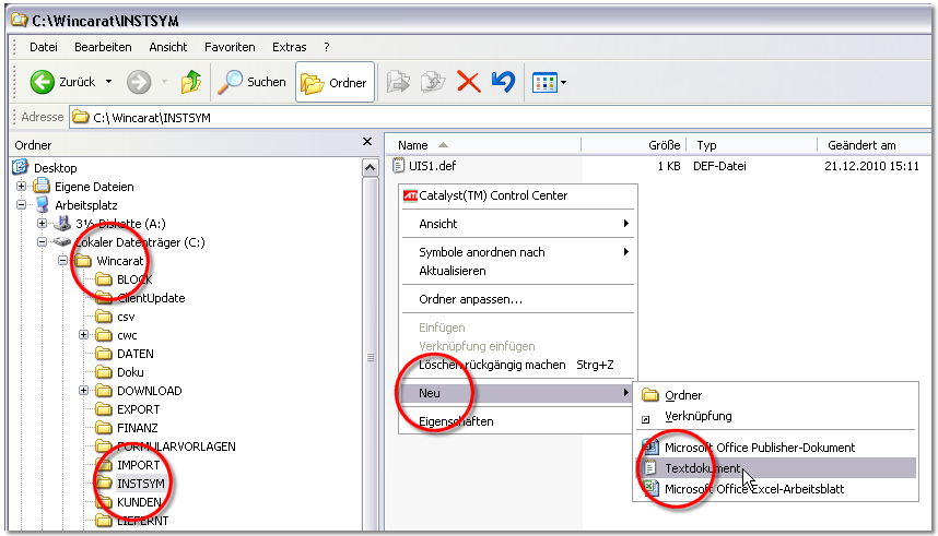
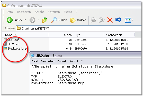
- Change to the directory INSTSYM of your CARAT installation and click Typically the LEFT mouse button is pressed once quickly, if not specified differently. Clicking will either mark an object, or when clicking on a button, the execution of the desired activity (e.g. OK, Cancel, Close). with the right mouse button In dialogue windows you always find one or more buttons that can be activated by clicking on them. Typical functions for buttons are e.g. OK, Cancel, Apply. Buttons are always activated by a single click with the left mouse button. in a free area within the directory. Please first select via the context menu In almost all Windows programs a click with the RIGHT mouse button opens a context menu containing a list of commands that are commonly the next step of a procedure. the entry New and subsequently the entry to create a Text document.
- Now, a new text file will be added Addition (in Latin: addere) is one of four basic operations in arithmetic. In primary school and in common language it is the expression used for the adding of two or more numbers. automatically. The name of the file given by default is marked and can be overwritten directly.
- We assign the name uis2.def, for the new definition file for our example. See also: User defined Installation Symbols
- A note will appear as soon as you confirm the modification of the file name, you can confirm this note with Yes. The definition file can now be complemented with the necessary parameter.
A title, the type as well as the size (W/H/D) of the installation symbol must always be stated for each self created installation symbol. These specifications should usually be entered directly after creation of a new definition file. Optionally The word option (from Latin: optio = free will) used in computing means a choice. In CARAT it is normally used with a list box., as of V2022.15.0.0, you can now also store your own colour value with the parameter RGB RBG is the abbreviation for the colours red, green and blue. A specific colour in a surrounding field can be easily described using an RGB-value. For example, a pure red has an RGB-value R=255, G=0, B=0. text for the title.
- Because we would like to create in our example, an installation symbol for a power socket with switch, we have chosen as title "Power socket (switchable)". The title will be displayed as quick help (Tool tip) as long as the mouse pointer is situated on the button in the extended symbols area. The title is furthermore displayed in the legend of the installation plan.
- Since it is a socket, we enter ELECTRO as type for the installation symbol.
- Enter WATER as type, if you want to assign a symbol to the sanitary range.
- The symbol should have a size of 80 x 80 x 10 mm (W/H/D).
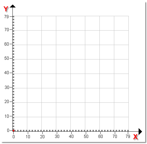
The first two values of the parameter W/D/H define a coordinates grid, which is necessary for the creation of the pictogram. Thereby, the width stands for the X-axis and the height for the Y-axis of the coordinates grid. To create an installation symbol with the size 80 x 80 mm, you define in the parameter W/H/D the size (80,80,10). Thus, an area of 80 x 80 Pixel Pixel or picture element identifies both, the smallest unit of digital raster graphics and the display of these graphics on a monitor with raster activation. (in the graphic 80 X 80 millimetre) will be created for this installation symbol. The following illustration should clarify this for you.
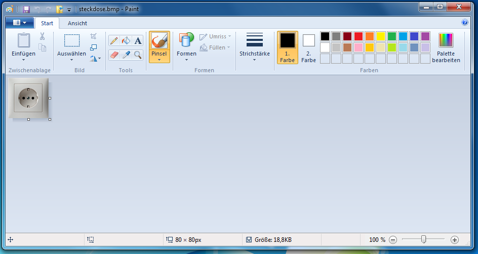
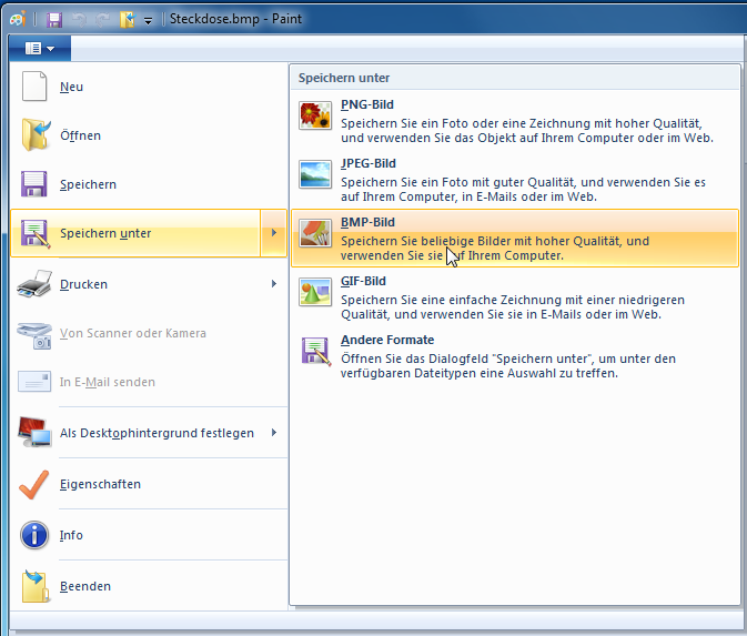
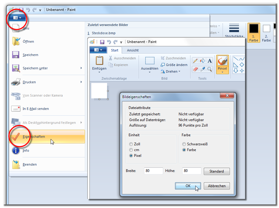
To be able to graphically design also for the perspective an installation symbol, you need a raster graphic A raster graphic, also named pixel graphic (Bitmap), is a way to describe an image in a data form readable by computers. Raster graphics exist of arrangements of pixels (picture points) in a grid form, each being assigned a colour. The key features of a raster graphic are the width and height in pixels, also know as resolution, as well as the colour depth. in BMP Windows bitmap (BMP) is a two-dimensional raster graphics format, which was developed for the operating system Microsoft Windows and OS/2, and was introduced with Windows 3.0. The file-extension is *.bmp. format The format or formatting (Latin, forma) is designated in word processing as the design of the text document. In this case meaning the selection of character fonts and character style such as bold or italics.. You can use the graphics program Paint for the conversion of the graphic, this program should usually be available on every Windows computer.
- With it, the graphic can be saved in BMP-format by using the Save as... function.
- For our example are in the parameter W/H/D the sizes (80,80,10) specified, meaning width 80 mm, height 80 mm and depth 10 mm.
- Additionally we have defined the file with the name "power socket.bmp" via the parameter PSV-Bitmap, which also has been saved in the sub-directory INSTSYM. Please note, that the filename for the graphic in the definition file always should be written between two quotation marks.
- Based on the specifications in the parameters PSV-Bitmap and W/H/D, a block with the corresponding dimensions will be created in the perspective, and automatically allocated with the raster graphic stated.
With a little exercise, also more complex pictograms can be created fairly quickly. A pictogram can be made up of lines, circles and circular arcs. These graphical parts must be specified in the definition file as coordinates. It is the easiest, if you first create the pictogram with a graphics program and determine the coordinates in the process. The previously mentioned graphics program Paint is also for this purpose adequate enough.
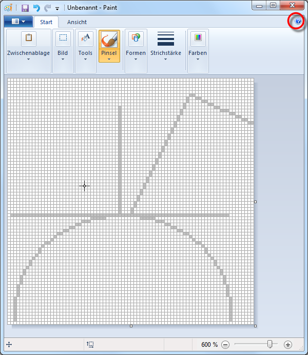
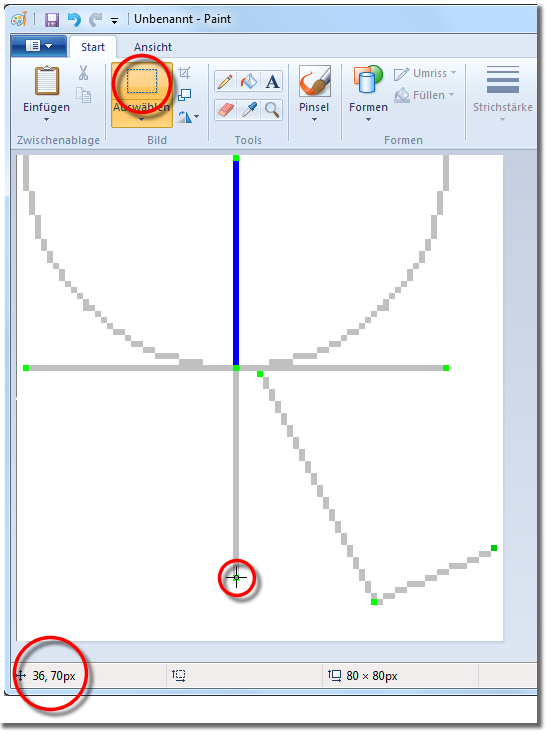
- The following illustration shows a symbol that contains 5 elements, four lines and a circular arc.

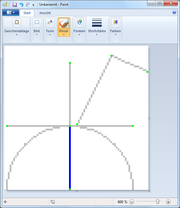
Every line in the definition file has to be specified with a start and a finish coordinate, as you have learned from the principles mentioned before. The semi-circle needs besides the coordinates for the centre point, also the radius as well as the start and end angle. Following we would like to explain you how you can determine these coordinates fairly simple.
- Define first the size of the required drawing area. Enter the width and height of the area in the relevant dialogue Dialogue, dialogue windows or dialogue fields are special windows in software applications. Dialogue windows are displayed by application programs in different situations to request input or confirmation from the user.. Please note that Pixel has been selected as units.
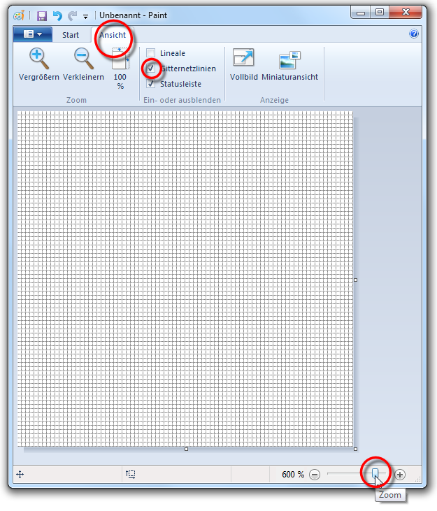
- We would advise you to enlarge the drawing area so you will be able to draw more easily. For this, you can change the zoom factor. If not done so already, you should activate the checkbox A checkbox is a standard element in a graphic user interface. A checkbox has, in most cases, two states (set or not set). These usually correspond to a yes/no selection. gridlines via the view index card Some dialogue windows are too voluminous, therefore the functions are separated into indexed groups. The subgroup names typically appear on the tab of the index card at the top of the dialogue and can be selected by clicking on the appropriate tab., this will facilitate you when placing the graphical elements in the area.
- Subsequently you can design the desired pictogram with the available drawing functions lines or circle. Please use the available help in case of questions regarding the handling.
- We have highlighted the coordinates for the lines and the circular arcs in colour, so you can recognise them better. The coordinate points have been marked in green, and the radius in blue.
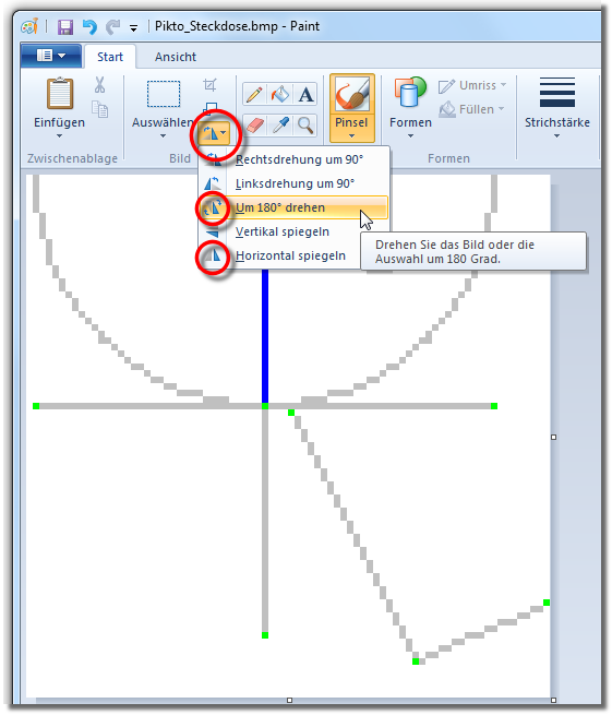
Most drawing programs, like Paint too, have the characteristic that the zero-point of the drawing area is always located top left. Since the coordinates for CARAT have to be stated from bottom left, it would mean that you would have to create the pictogram mirrored and upside down to be able to subsequently determine the coordinates.
However, most drawing programs offer a clearly simpler solution: First draw the pictogram as it later should look like in CARAT. Then you can flip and rotate it 180° using simple functions. Thus you can subsequently determine the coordinates, as they should be entered in the definition file.
- Please simply use the select tool, to determine the coordinates. Wit it, the mouse pointer will be displayed as small cross line, with which you can point on the individual coordinate points. Thus, you can read off the exact position in the grid system at the bottom border. In the process, even the sequence of the coordinates is correct, so you can assume the individual values exactly like that in your definitions file.
The coordinates determined can now be entered, for the individual graphical elements, in the definitions file. You should also always specify a colour value via the parameter RGB for the parameters for the graphical elements, as we have described in the principles. The whole pictogram in our example should be drawn in red.
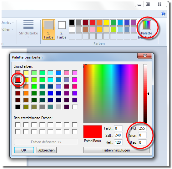
- You can use a simple function in Paint to determine the RGB-value for any colour. For this, open the Edit colours dialogue. After selecting a colour in the upper left or the right area you can read out the RGB-value in the bottom right area. As you can see from the following illustration, the RGB-value of the colour we have selected is made up of the values Red = 255, Green = 0 and Blue = 0.
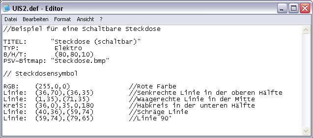
- The following picture displays the finished definitions file. As you can recognise is first the colour red defined via the parameter RGB with the values (255,0,0). Subsequently are the individual lines with their respective start and end coordinates stated. Behind each individual parameter, we have added a relevant comment for better orientation.
- We have recorded the parameter Circle with the values (36,0),35,0,180. The centre point of the circle is defined with the coordinates (36,0) and the radius with the next value 35. However, these specifications alone would define a full circle.
- However, since only a semi-circle is required for this installation symbol, the absolute angle, between which the circular arc should be drawn, is specified additionally. In this example a circular arc between the angles 0° and 180° should be drawn.
Small Excursion: Angle Specifications
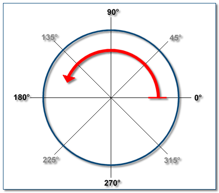
Additionally, the absolute angle specifications for the start and the end of the circular arc required are necessary to be able to design a circular arc via the parameter CIRCLE. The 0° position of the circle is always situated at the right, on the 3 o'clock position. To define a circular arc, first the start angle and then anticlockwise the end angle should be determined. For our power socket symbol we need the upper half of a circle and we have therefore specified as start angle 0° and as end angle 180°.
