User defined Installation Symbols
The installations symbols that are needed as standard for an electro or sanitary plan are already available in CARAT. The design of the installation symbols is based on the in Germany valid norm for electrical graphic symbols according DIN EN 60617 - graphical symbols for connection diagrams - respectively on DIN IEC 60617. If you need more electro or sanitary symbols for your installation plans, you have the possibility to create user defined installation symbols yourself.
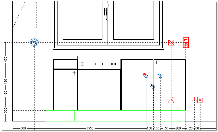
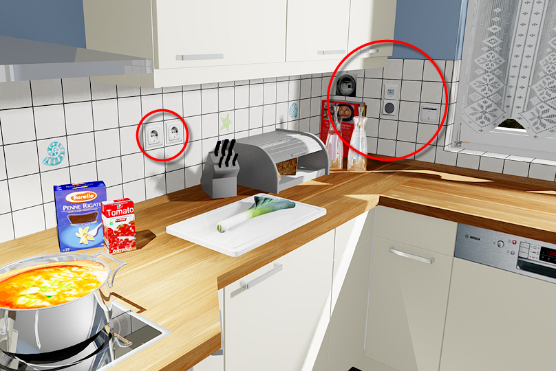
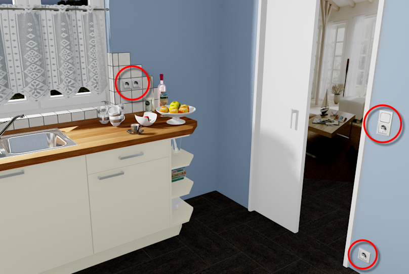
Examples of User Defined Installations Symbols
|
Installation plan - Front |
Display in the Perspective |
|
|---|---|---|
The pictures are intended to demonstrate the additional Addition (in Latin: addere) is one of four basic operations in arithmetic. In primary school and in common language it is the expression used for the adding of two or more numbers. possibilities that will arise from the self-created user defined installations symbols. You can for example create your own symbols or also simplified pictures in any size and colour combination for the installation plan. On demand, you can additionally assign an actual graphic as image file to the user defined installation symbols, so that the planned installation symbols increase the realistic space impression in the perspective.
Working Layer Installation Plan
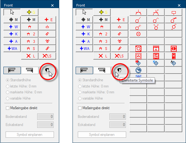
First is, for a better overview, the area for the user defined installations symbols not displayed in the dialogue Dialogue, dialogue windows or dialogue fields are special windows in software applications. Dialogue windows are displayed by application programs in different situations to request input or confirmation from the user. Installation plan. Click Typically the LEFT mouse button is pressed once quickly, if not specified differently. Clicking will either mark an object, or when clicking on a button, the execution of the desired activity (e.g. OK, Cancel, Close). on the button In dialogue windows you always find one or more buttons that can be activated by clicking on them. Typical functions for buttons are e.g. OK, Cancel, Apply. Buttons are always activated by a single click with the left mouse button. symbol for the extended symbols, to display the user defined installation symbols. As long as you have not created any user defined installation symbols, you will see here at first only the empty buttons. The setting of the dialogue is saved user specific, so that the dialogue always will open as displayed the last time. See also: The Installation Plan
The Fundamentals of Creating a Definition File
To be able to employ the user defined installation symbols as versatile as possible, the definition of an user defined installation symbol takes place each via an own file. All information, that is necessary for the design a symbol, is entered in this definition file. A definition file is a simple text file, that you can create and edit with the any text editor program. The dialogue Installation plan can accommodate up to 51 own installations symbols. See also: Creating a definition file
- The definitions file must be saved in the subdirectory INSTSYM of your CARAT installation.
- The file name of the definitions file must be assigned according the following pattern:
- The file name always has to start with the letter combination uis.
- Subsequent a number, with which you can define the sequence of the symbols, follows.
- As file extension the name .def must be assigned.
|
Example: |
|---|
|
uis1.def, uis2.def, uis3.def ...... uis49.def, uis50.def, uis51.def |
Only a few specifications in a defined format The format or formatting (Latin, forma) is designated in word processing as the design of the text document. In this case meaning the selection of character fonts and character style such as bold or italics. are necessary for the creation of a definition file:
- A meaningful name for the installation symbol.
- The assignment to the range electro or sanitary.
- The specification of the display size of the symbol in millimetre.
- A raster graphic A raster graphic, also named pixel graphic (Bitmap), is a way to describe an image in a data form readable by computers. Raster graphics exist of arrangements of pixels (picture points) in a grid form, each being assigned a colour. The key features of a raster graphic are the width and height in pixels, also know as resolution, as well as the colour depth. for the display in the perspective, if required.
- For multi coloured symbols, the colour specification in the form of RGB RBG is the abbreviation for the colours red, green and blue. A specific colour in a surrounding field can be easily described using an RGB-value. For example, a pure red has an RGB-value R=255, G=0, B=0. values.
- A template, so that a pictogram can be created for the desired symbol.
An example of a power socket with switch should be created as pictogram, to clarify the configuration A configuration designates the specific program settings or hardware components in a computer. of the definition file. Furthermore should the installation symbol for the perspective obtain an actual image of a power socket. Following you can see the desired result.

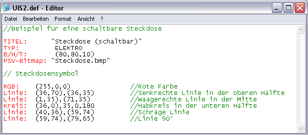
The following picture shows the definition file with which we have created this power socket with switch as user defined installation symbol. We have coloured the different specifications to help you with the orientation in the definition file. The colours should accentuate the three major area's of a definition file.
|
Colour |
Description |
|---|---|
|
Red |
The red coloured texts deal with Parameter, which are needed to create an user defined installation symbol. Depending on the purpose for which a symbol is created are not always all parameter necessary. |
|
Black |
The black text deals with the Data, that create the installation symbol. |
|
Green |
The green coloured texts deal with Comments, that you can ad Addition (in Latin: addere) is one of four basic operations in arithmetic. In primary school and in common language it is the expression used for the adding of two or more numbers. as needed. A comment always has to be preceded by two slashes (//). |
| Parameter: | Description: | Example: |
|---|---|---|
|
TITLE |
A title serves as name for the installation symbol and must always be written between Two quotation marks. The title will also be displayed as quick help (Tool tip) as long as the mouse pointer is situated on a button in the extended symbols area. This title is also used for the legend in the installation plan. |
"Power socket (switchable)" |
|
TYPE |
You specify if the installation symbol should be assigned to the electro (ELECTRO) or sanitary (WATER) range via the Type. This is important, because you can opt to display only electro or sanitary connections in the installation plan. | ELECTRO |
|
W/H/D |
The width, the height and the depth of the area that the installation symbol should take up is specified by the specification W/H/D. The specification of the depth will of course only be used for the perspective, whereby a cuboid is created in the specified size. The size specification must be made in millimetre and between two parentheses. The individual values must be separated by a comma. | (80,80,10) |
|
PSV-Bitmap |
You can specify a raster graphic with the parameter PSV-Bitmap, by which the installation symbol can also be displayed in the perspective. The file name must likewise be entered between two quotation marks. Please note that only graphics in BMP Windows bitmap (BMP) is a two-dimensional raster graphics format, which was developed for the operating system Microsoft Windows and OS/2, and was introduced with Windows 3.0. The file-extension is *.bmp. file format can be used. | "Power socket.bmp" |
|
RGB |
To colourise the following graphical elements for the pictogram you can specify a RGB-value via the parameter RGB. The colour specification must be made between two parentheses. The single colour values have to be separated by a comma. The colour specification is stated according the following pattern: (Red,Green,Blue). | (255,0,0) |
|
RGB-TEXT |
New: from version V2022.15.0.0 you can specify an RGB value with the parameter RGB-TEXT if you want to colourise the designation for the installation symbol differently from the graphic elements. The colour specification must be made between two parentheses. The single colour values have to be separated by a comma. The colour specification is stated according the following pattern: (Red,Green,Blue). |
(0,0,222) |
|
Line |
By the parameter W/H/D is an area is defined in which a line can be drawn by entering two coordinates which stand for the start and end point. The parameter Line can be used any number of times and also be combined with the parameter RGB, to be able create also more complex pictograms. Both coordinates for the start and end point have to be noted each between parentheses. The value within the parentheses as well as both coordinates have to be separated with a comma. The coordinates are stated according the following pattern: (X,Y),(X,Y). |
(1.35),(71.35) |
|
Circle |
The parameter Circle is the second graphical element. A centre point and a radius have to be stated to be able to draw a circle. If needed also only a reference circle can be drawn by subsequently stating a start and finish angle. The coordinates for the middle point have to be noted between parentheses and all values have to be separated with a comma. The specification of a full circle is stated according the pattern: (X,Y),Radius. The specification of a reference circle is stated according the pattern: (X,Y),Radius,Start angle,Finish angle. |
(36.0),20 (36.0),20,0,180 |
Example files
For you to be able to comprehend the hitherto explanations more easily, following we would like to make available three example files, which you can save in your CARAT installation. Herewith it concerns the necessary definition files for the installation symbols as well as the raster graphics for the design in the perspective. Save the definition file as well as the corresponding raster graphic in the INSTSYM directory of your CARAT installation. The relevant symbol will then be available in the area of the extended symbols of the installation plans, after a restart of CARAT.
|
Power Socket with Switch |
|
|---|---|

|
|
|
Hot water supply |
|

|
|
| Water meter | |

|
|
