The Installation Plan

A clear and reliable installation plan simplifies the cooperation with your workmen who have to prepare for the installations of a new build-in kitchen in advance, and you can profile yourself towards your customer with an extra service.
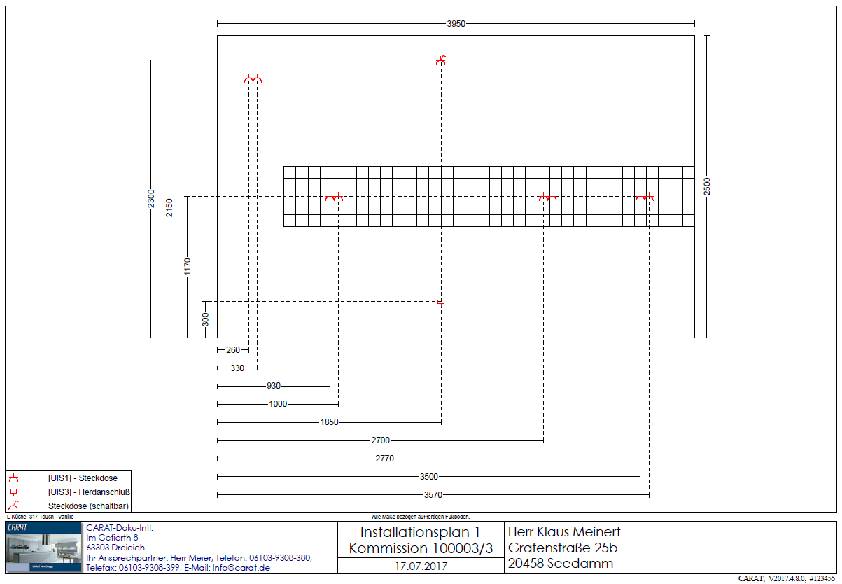
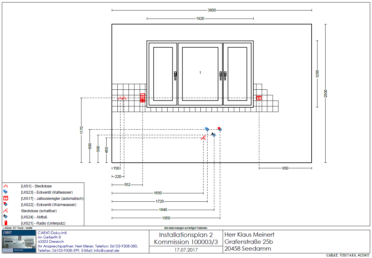
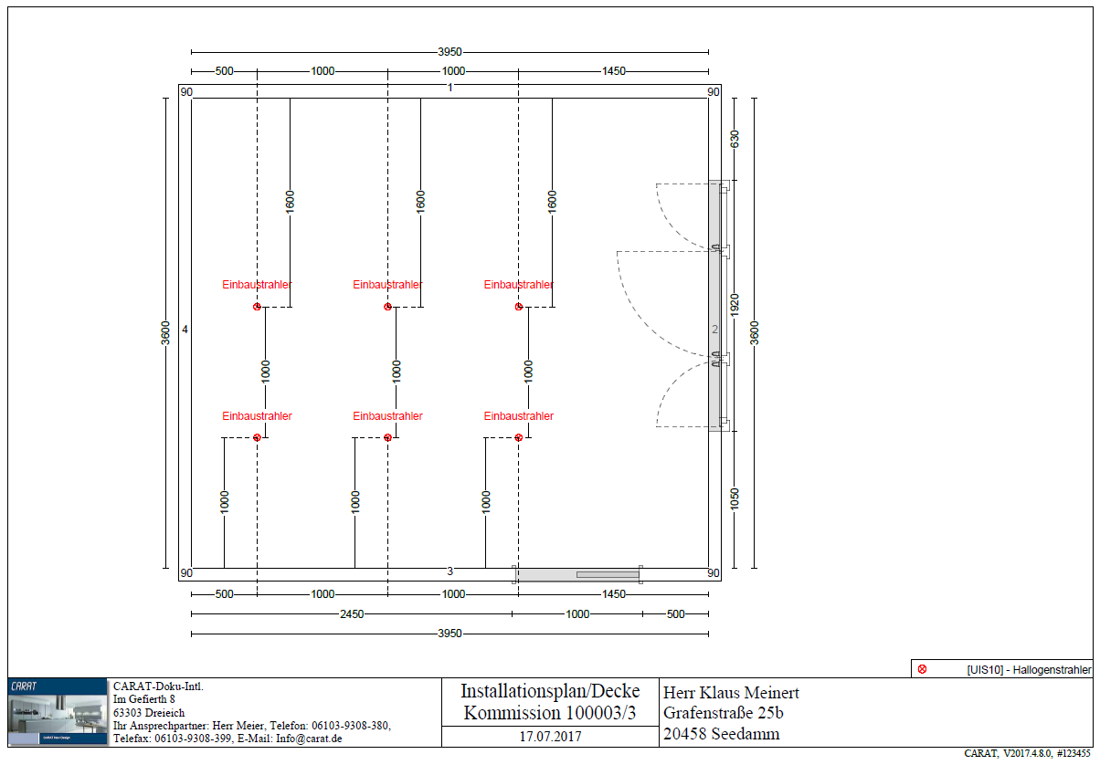
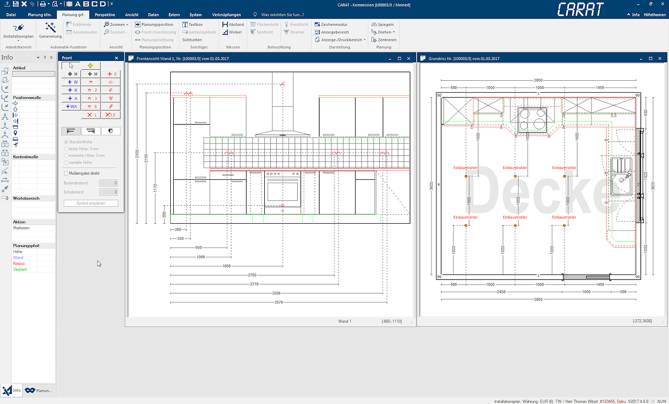
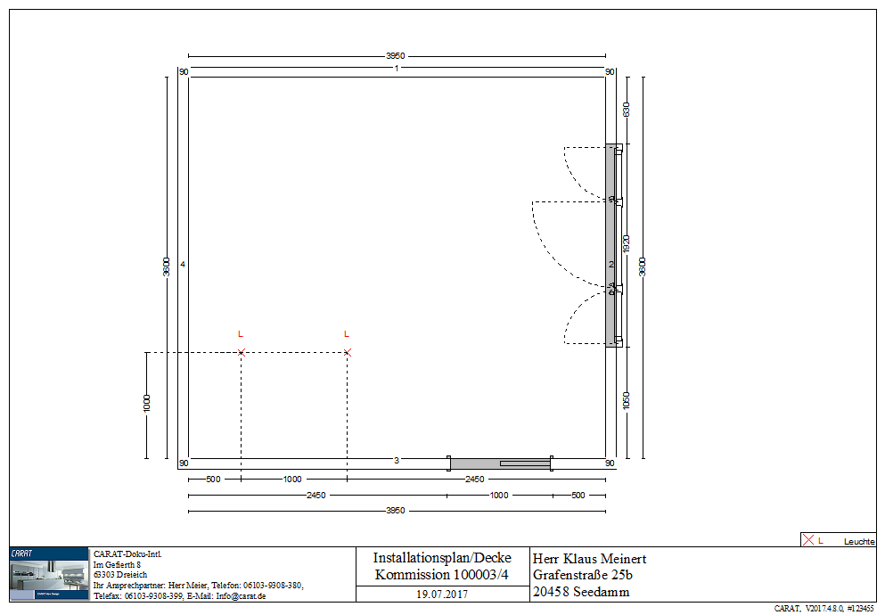
That is why CARAT has a separate working layer Because the ranges of a design often overlap in the floor plan (e.g. plinth, worktop, carcase etc.) these article groups are classified into working layers., via which you can prepare relevant plans for electro and sanitary installations. The working layer Installation plan offers you the possibility to create installation plans for walls as well as the floors or also for the ceiling.
|
Installation plan - Front |
Installation plan - Front |
Installation plan - Ceiling |
|---|---|---|
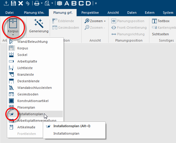
- You can set the working layer installation plan by using the working layer group, which is located on the complete left side of the Planning graph. index card Some dialogue windows are too voluminous, therefore the functions are separated into indexed groups. The subgroup names typically appear on the tab of the index card at the top of the dialogue and can be selected by clicking on the appropriate tab. in the menu ribbon.
- Then, a special dialogue Dialogue, dialogue windows or dialogue fields are special windows in software applications. Dialogue windows are displayed by application programs in different situations to request input or confirmation from the user. will open, via which you can plan the symbols for electro, water and gas as well as wall breakthroughs.
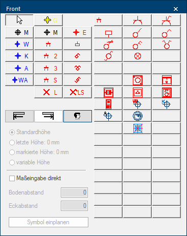
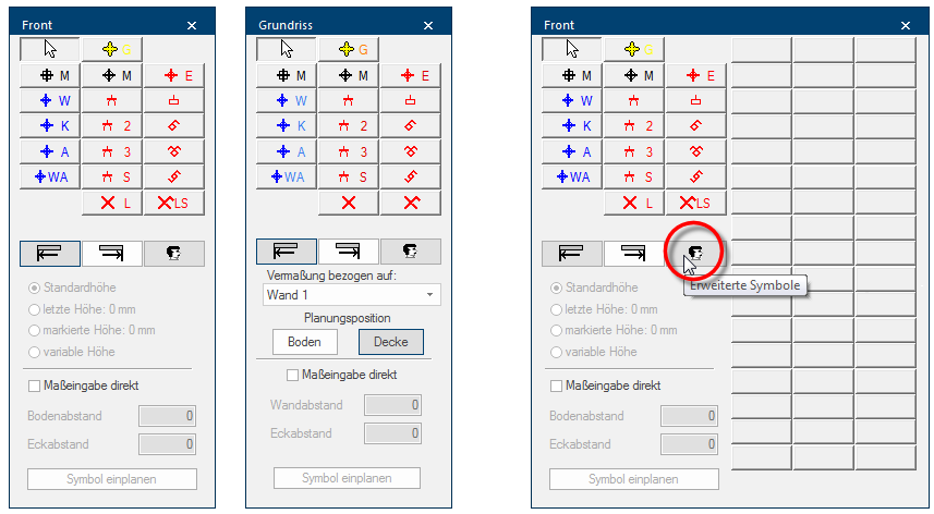
The dialogue for creating installation plans is divided in three main area's. The functions available are automatically customised, depending on the view in which you want to create an installation plan (floor plan or front view).
- All installation symbols, that are already provided by CARAT as standard, are shown in the upper part of the dialogue.
- You will find the functions, necessary for planning in an installation symbol, underneath the standard symbols.
- By using the Extended symbols symbol button In dialogue windows you always find one or more buttons that can be activated by clicking on them. Typical functions for buttons are e.g. OK, Cancel, Apply. Buttons are always activated by a single click with the left mouse button., an additional Addition (in Latin: addere) is one of four basic operations in arithmetic. In primary school and in common language it is the expression used for the adding of two or more numbers. area with extra, also self created, installation symbols can be shown or hidden. See also: Installation symbols, User defined Installation Symbols
|
Symbol/Function |
Description |
|---|---|
|
|
Gas connection |
|
|
Wall breakthrough, angular |
|
|
Wall breakthrough, round |
|
|
E-appliances connection |
|
|
Power socket |
|
|
Twin power socket |
|
|
Triple power socket |
|
|
Fused power socket |
|
|
Cooker connection |
|
|
Switch |
|
|
Serial switch |
|
|
Rocker switch |
|
|
Lamp |
|
|
Lamp with switch |
|
|
With this symbol you define that the installation symbol should be measured from the left wall corner. |
|
|
With this symbol you define that the installation symbol should be measured from the right wall corner. |
|
|
By using this button, you can fold or unfold the area of the extended symbols. See also: Installation symbols, User defined Installation Symbols |
|
Standard height |
With this option The word option (from Latin: optio = free will) used in computing means a choice. In CARAT it is normally used with a list box., the installation symbol will be planned in the front view at the height that is defined as standard height for this symbol. See also: Installation symbols |
|
Last height |
With this option, the installation symbol will be planned in the front view at the same height of the installation symbol planned in last. |
|
Marked height |
With this option, the installation symbol will be planned in the front view at the same height of the last marked installation symbol. |
|
With this option, the installation symbol can be placed in the front view at any height. |
|
|
Measuring based on |
With this list box If several options are provides for one function provides, are these often shown in a list. Please click on the little black triangle in the right margin to select the desired option., the wall, on which the measuring for the installation symbol in the floor plan should be based, can be selected. |
|
Planning position |
With these two buttons, you can switch between the installation plan for the floor and the ceiling. |
|
Enter measurement direct |
By using this option, you can enter a defined measurement directly. |
|
Floor distance |
Enter here the distance from the floor till the middle of the installation symbol. |
|
Corner distance |
Enter here the distance from the selected wall of the front view till the middle of the installation symbol. |
|
Wall distance |
Enter here the distance from the selected wall in the floor plan till the middle of the installation symbol. |
|
Plan symbol |
By using this button, the selected installation symbol, with the measurements entered, can directly be taken over in the design. |
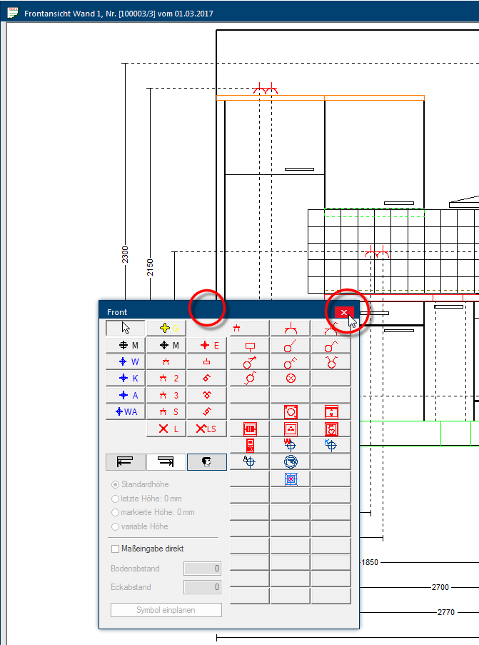
- In order for the dialogue not to be in the your way, you can position it by moving the mouse pointer on the blue title bar of the dialogue and then move the mouse while pressing the left mouse button, and thus positioning the dialogue to another position on the working area.
- To close the dialogue, click Typically the LEFT mouse button is pressed once quickly, if not specified differently. Clicking will either mark an object, or when clicking on a button, the execution of the desired activity (e.g. OK, Cancel, Close). in the title bar of the dialogue on the X on the right, thereupon also the working layer cabinet will be re-set again automatically.
This is how you create an installation plan
To create an installation plan, first open the necessary view and switch then to the working layer installation plan. Customise the size of the view according your needs and move the dialogue Installation plan to a location where the dialogue bothers you the least. It can be useful to create an user defined view for this recurring procedure, thus being able to quickly position the views desired and to get the necessary space for the extra dialogue. See also: The User defined Views
To quick and simple apply an installation symbol in a drawing it is useful to know the relevant position, meaning the distance to a wall corner and the distance to the floor. However, you can position an installation symbol freely with the mouse at any time or you can abide by reference dimensions when positioning in the height, or move an installation symbol afterwards to a different position.
Entering a measurement directly is most suited when you know the position for an installation symbol. Then, based on precise position specifications, you can quickly place an installation symbol at the position required by using the Enter measurement direct option.
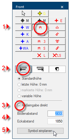
- First select the installation symbol with the left mouse button (1).
- Subsequently select the fitting side of the wall for the corner distance (2).
- You should specify the required wall as reference for an installation symbol in a floor plan.
- Activate the Enter measurement direct option (3) and enter the value for the distance to the floor distance or the wall distance as well as the corner distance (4).
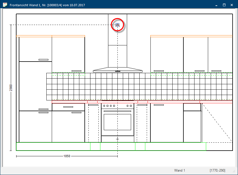
- Click on the Plan symbol button to apply the installation symbol in the installation plan (5).
- The installation symbol will then be placed at the specified location in the installation plan.
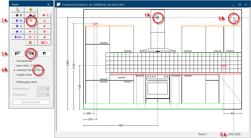
By using the Standard height option, you can plan in an installation symbol in the front view automatically on the saved standard height for that respective installation symbol. You only have to specify the corner distance from the left or right wall side. See also: Installation symbols
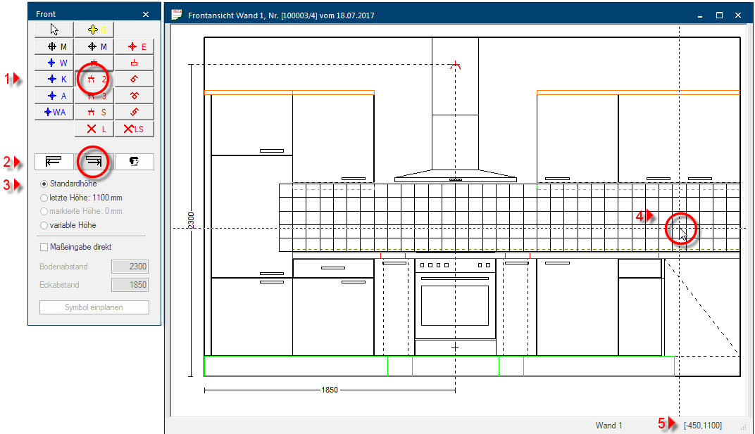
- First select the installation symbol with the left mouse button (1).
- Subsequently select the fitting side of the wall for the corner distance (2).
- The Standard height option will automatically be pre-set (3).
- Use the mouse to move the dotted cross line to the position at which you want to place the installation symbol (4).
- To this you are continuously displayed two measurements, at the bottom right side of the dialogue, via which you can read of the current position of the cross line. The left measurement defines the corner distance and the right measurement the floor clearance (5).
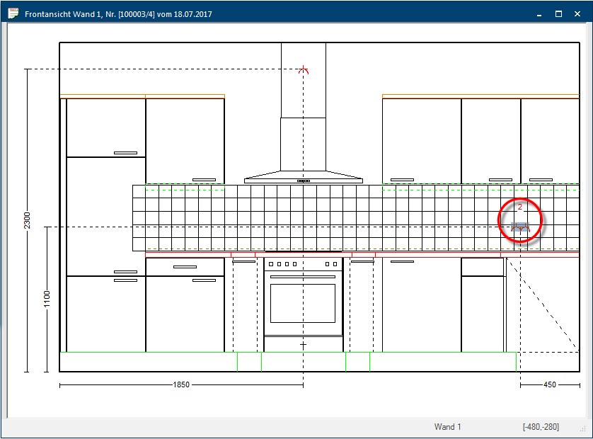
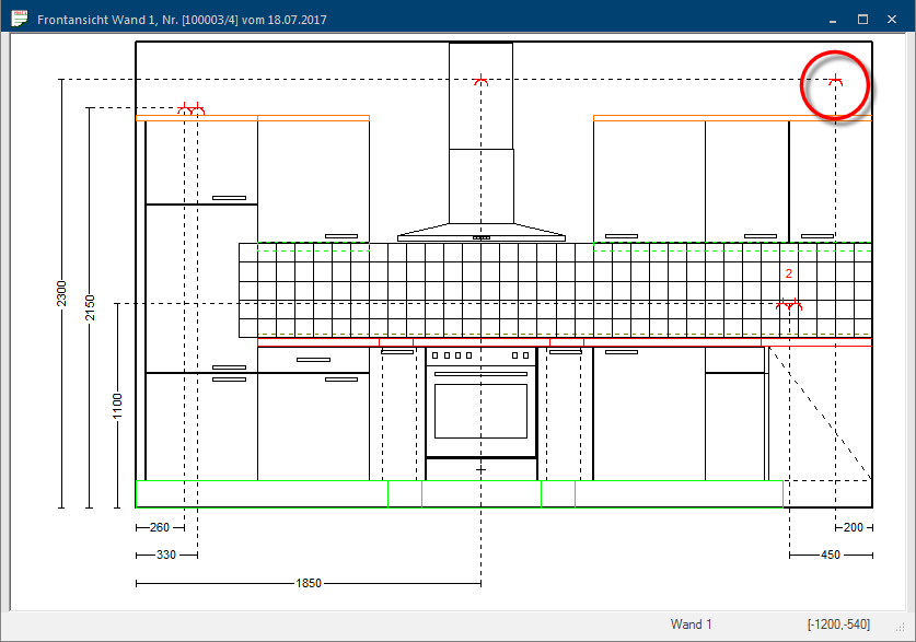
- When you have reached the position desired, click either with the left mouse button or on the enter key The enter key (also known as return or enter) is located on the right side of the letter part of your keyboard and is usually labelled with an arrow pointing to the left. This key causes a line break when used in word processing and is also used in software programs to confirm the currently marked button (usually OK or Cancel)., to place the installation symbol.
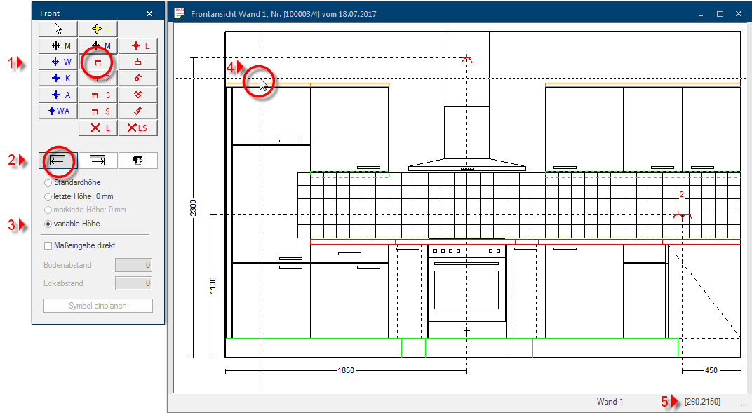
The option Variable height is available when the position of an installation symbol can be freely defined by you. If the option is activated, you can place the cross line at any position desired.
- First select the installation symbol with the left mouse button (1).
- Subsequently select the fitting side of the wall for the corner distance (2).
- Then select the Variable height option (3).
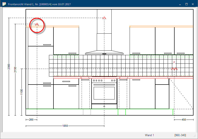
- Use the mouse to move the dotted cross line to the position at which you want to place the installation symbol (4).
- To this you are continuously displayed two measurements, at the bottom right side of the dialogue, via which you can read of the current position of the cross line. The left measurement defines the corner distance and the right measurement the floor clearance (5).
- When you have reached the position desired, click either with the left mouse button or on the enter key, to place the installation symbol.
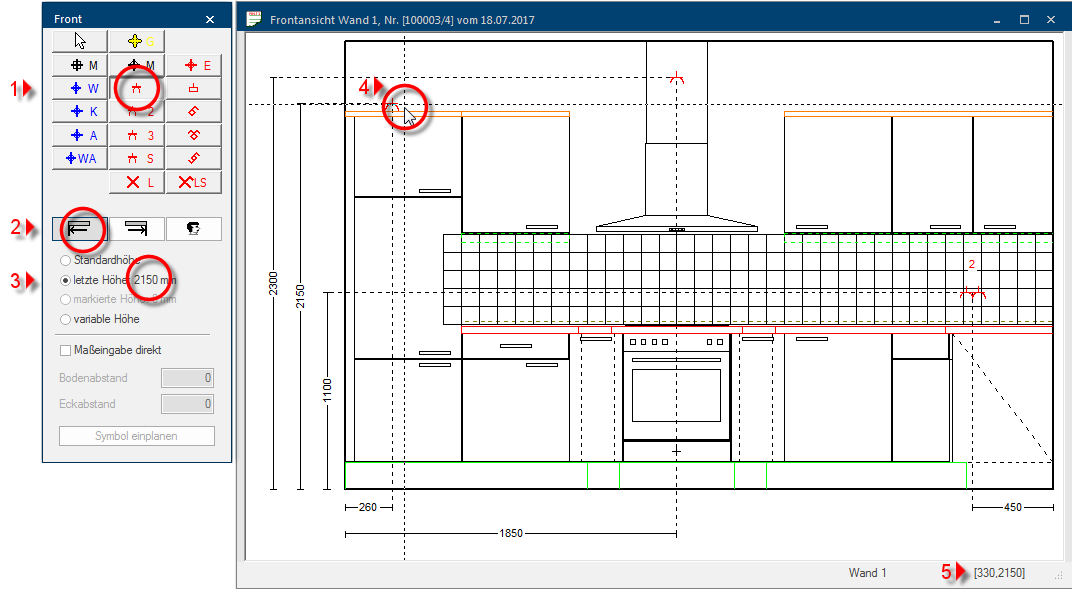
It always makes sense to use the Last height option, if you have previously planned in an installation symbol and subsequently want to plan in another symbol with the same floor clearance but with another corner distance.
- First select the installation symbol with the left mouse button (1).
- Subsequently select the fitting side of the wall for the corner distance (2).
- Then select the Last height option (3).
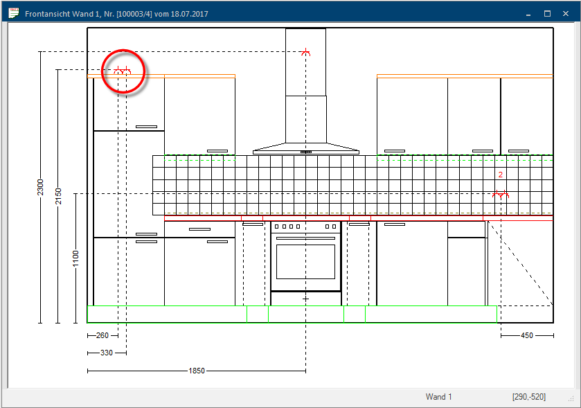
- Use the mouse to move the dotted cross line to the position at which you want to place the installation symbol (4).
- To this you are continuously displayed two measurements, at the bottom right side of the dialogue, via which you can read of the current position of the cross line. The left measurement defines the corner distance and the right measurement the floor clearance (5).
- When you have reached the position desired, click either with the left mouse button or on the enter key, to place the installation symbol.
It always makes sense to use the Marked height option, if you want to plan in an installation symbol with the same floor clearance but with an other corner distance as another installation symbol that you have planned in previously.
- First mark an installation symbol on whose height you want to plan another symbol (1).
- Then select the new installation symbol with the left mouse button (2).
- Subsequently select the fitting side of the wall for the corner distance (3).
- Then select the Marked height option (4).
- Use the mouse to move the dotted cross line to the position at which you want to place the installation symbol (5).
- To this you are continuously displayed two measurements, at the bottom right side of the dialogue, via which you can read of the current position of the cross line. The left measurement defines the corner distance and the right measurement the floor clearance (6).
- When you have reached the position desired, click either with the left mouse button or on the enter key, to place the installation symbol.
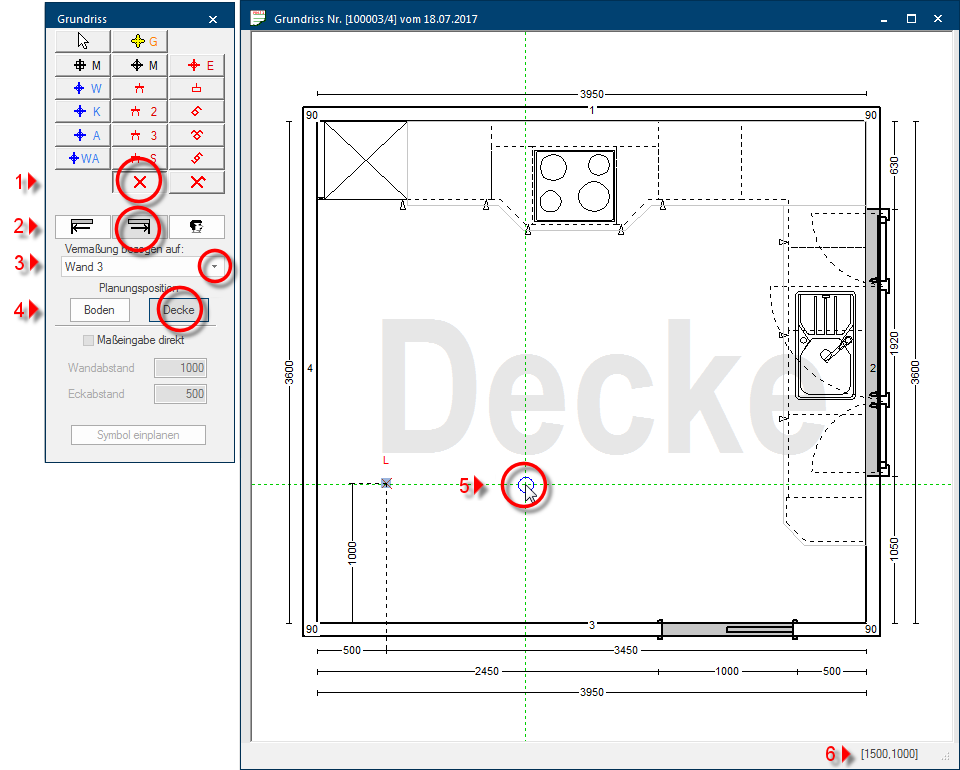
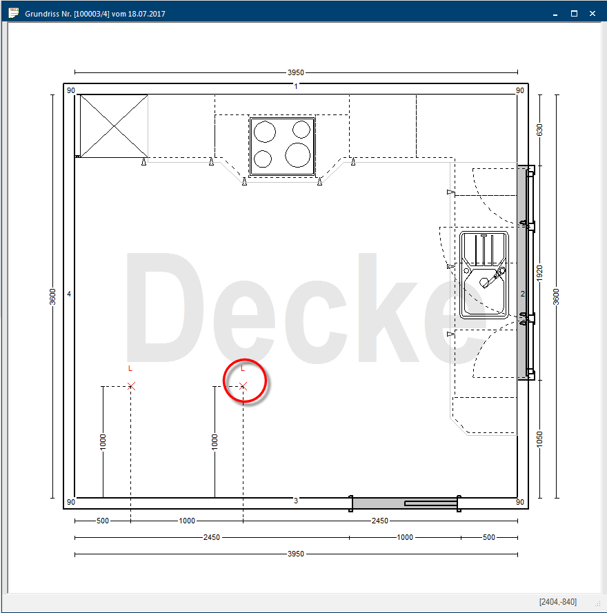
You have the possibility to create an installation plan for floor and ceiling separately via the floor plan. This allows you to create for example an installation plan for the floor, in which all necessary electro and sanitary connections for an island solution are included or you can prepare a tailor-made illumination plan for your customer.
No height specification is necessary for the installation plan floor or ceiling. However, in order to be able to plan an installations symbol, you need here also two dimensions to define the position of the symbol on the surface. For this, each installation symbol is planned in with a wall reference. With the wall distance, you specify the distance of the symbol to the selected reference wall. The corner distance specifies the distance from one of both wall corners of the reference wall.
- First select the installation symbol with the left mouse button (1).
- Subsequently select the fitting side of the wall for the corner distance (2).
- Then select the wall, that should be the reference for the dimensioning of the symbol (3).
- Set the range (floor or ceiling) where the symbol should be planned in (4).
- Use the mouse to move the dotted cross line to the position at which you want to place the installation symbol (5).
- To this you are continuously displayed two measurements, at the bottom right side of the dialogue, via which you can read of the current position of the cross line. The left measurement defines the corner distance and the right measurement the wall distance (5).
- For a more precise placement we would advice you to use the enter measurements direct function.
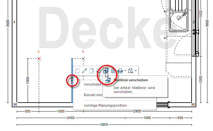
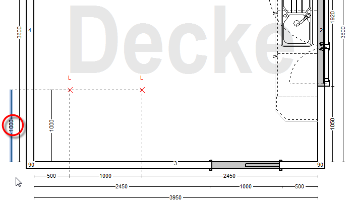
- The dimension chain for the corner distance to the reference wall will automatically de displayed automatically outside of the floor plan. The wall distance to the wall is always displayed near to the planned installation symbols. If necessary, you can move this dimension line also manually.
For an already planned installation symbol you can also conduct some modifications afterwards without having to plan in the symbol new.
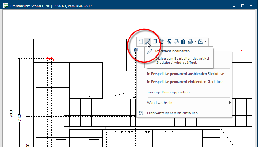
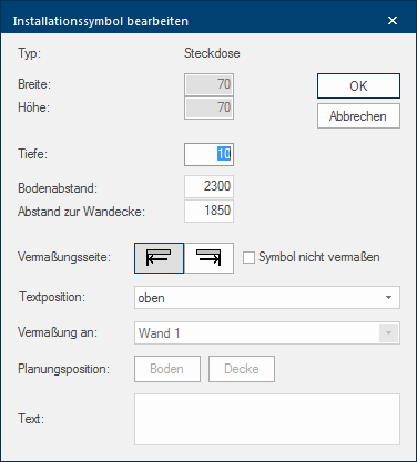
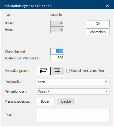
- To retrieve the Edit installation symbol dialogue please either double click A double click is, amongst other things, needed to open files and programs or to activate an operation or a command. If the mouse cursor points to the desired symbol, you should click the left mouse button twice in quick frequency. The mouse pointer should not be moved between these two clicks. on the installation symbol or mark the symbol and select the pencil symbol (Edit) from the context menu In almost all Windows programs a click with the RIGHT mouse button opens a context menu containing a list of commands that are commonly the next step of a procedure..
- Via the dialogue you can for example assign a special name for an installation symbol and arrange at which position the name should be displayed. You can also change the corner distance, floor distance or wall distance as well as the reference wall afterwards again.
|
Installation symbol - Front |
Installation symbol - Floor/Ceiling |
|---|---|
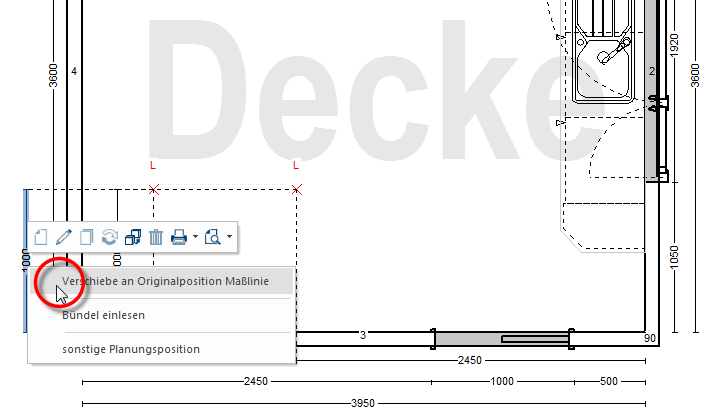
- To move a dimension line, please first click on that dimension line to mark it. Click subsequently with the right mouse button on the number of the dimension line and select the dimension line move function from the context menu.
- Now you can move the dimension line to the desired position while keeping the left mouse button pressed. Click one time on the enter key, to take over the new position of the dimension line.
- In case you would like to move the dimension line back to the original position, mark the dimension line and select the Dimension line Move back to original position entry via the context menu.
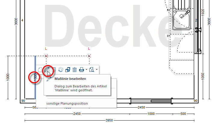
- After you have marked a dimension line, you can call up an edit dialogue for the marked dimension line via the pencil symbol (edit) in the context menu.
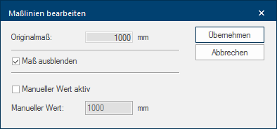
- You can use this dialogue to hide the marked dimension line or to change its values shown.
- If you activate the Hide option, the corresponding dimension line will be displayed in grey, to indicate that this dimension line wil not be shown in a printout.
