The Floor Plan
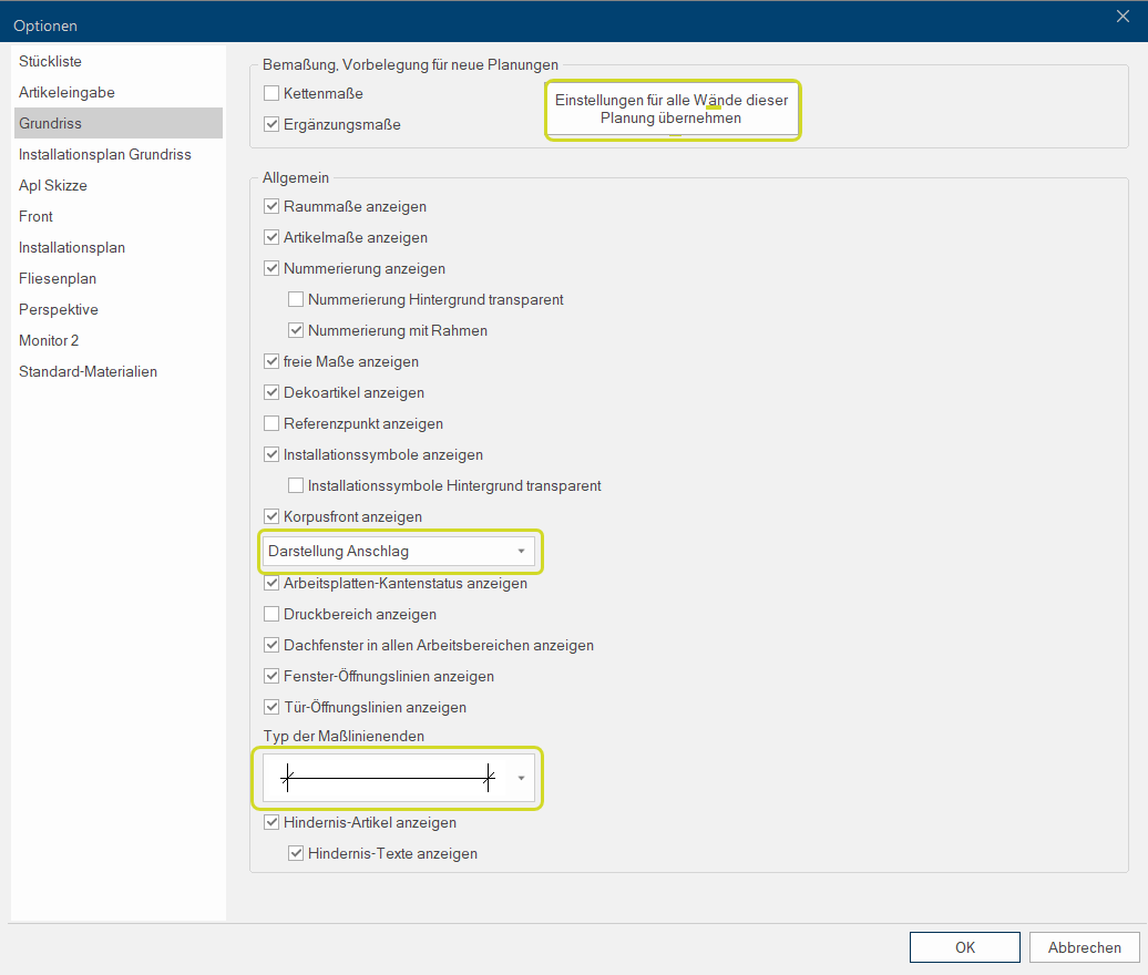
Via the Floor plan page you have several options The word option (from Latin: optio = free will) used in computing means a choice. In CARAT it is normally used with a list box. available for the modification of the view of the floor plan. Via these settings you can determine which graphical elements should be displayed in the floor plan window Programs and files are shown in so called windows in the operating system of the same name. In CARAT each view (e.g. floor plan, article input, front view, perspective etc.) opens its own window. Multiple windows can be shown simultaneously for processing. If changes are made in one of these windows, this has an automatic effect on all other windows.. All settings have to be done one time Per user and per server A server is a central computer in a designated network structure, from which the resources of the central computer can be accessed by multiple workstations (clients).. The data is stored Centrally, so access is always restricted to one user.
The by CARAT recommended settings for the floor plan options:
-
Change to design handing
-
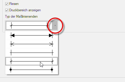
Adapt the shapes of dimension lines ends
See also: Screenshot
In the upper range Dimensioning - Default setting for new plans you have the possibility to determine on principle if besides the dimensioning of the individual room elements and articles also the additional Addition (in Latin: addere) is one of four basic operations in arithmetic. In primary school and in common language it is the expression used for the adding of two or more numbers. dimensions should be displayed or if the overlapping size chains should be displayed as chain dimensions.
The option Chain dimensions is always useful if many object at one wall have to be dimensioned, and they furthermore partially overlap each other. CARAT will at first try to plot each dimension of an object outside of the wall in such a manner that no dimension lines overlap. In unfavourable cases, with many articles, this can lead to many levels of size chains, where the individual measurements can no longer be assigned clearly to the belonging article.
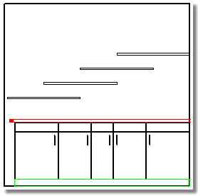
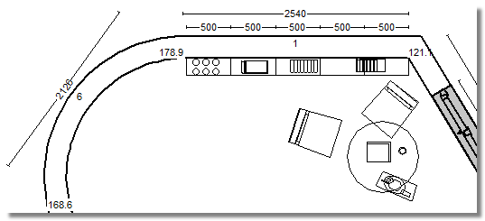
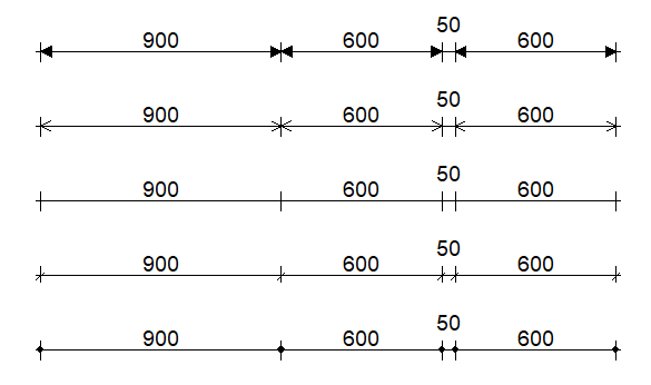
By chain dimensions can overlapping dimension lines in these case be merged to one dimension level. In the following example should a base unit row be dimensioned with the shelves mounted above. The shelves are always one metre wide and overlap each other half. The four shelves are therefore dimensioned by CARAT automatically on two separate dimension levels.
As soon as you activate the chain dimensions are all four measurements of the two dimension levels for the shelves being integrated. Now, every 50 cm the measurement points of the shelves are displayed as dimension. This allows for a significantly more compact arrangement of the dimensions.
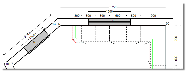
If no other settings have been made ,CARAT will first measure all room elements, like walls, doors, windows and most of the cabinets. You can recognise this kind of dimensioning based on the picture of a floor plan. However, some remaining dimensions to the wall corners are missing in the dimension chains for the cabinets and the windows.
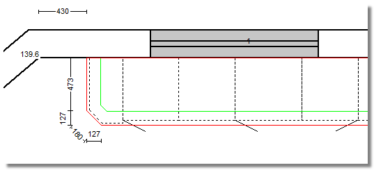
If additional dimensions is activated, the missing sizes are also supplemented for each dimension chain. Based on the following picture you can recognise that the dimension chain for the cabinet has been supplemented with the residual measurement to the left wall corner. For the dimension chain of the window are both lateral sizes supplemented.
You can define which sizes should be displayed in the selected view via the view options Show room dimensions and Show article dimensions. All room elements and cabinets that create own dimension lines are then calibrated according their position in the view. The missing dimensions for the displayed measurement levels can be shown additionally by using the previously described option additional dimensions, if required.
Show numbering
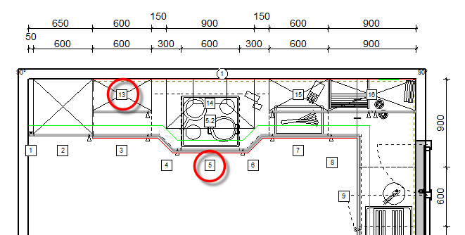
With this option you can define, if for individual furniture pieces their own position number from the parts list should be displayed additionally. Especially when you work with a window layout, by which several graphical windows as well as the parts list are open, can displaying the position number in the relevant view ease the identification of the respective article. See also: The User defined Views
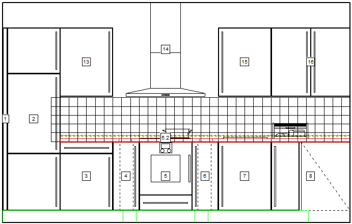
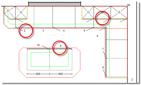
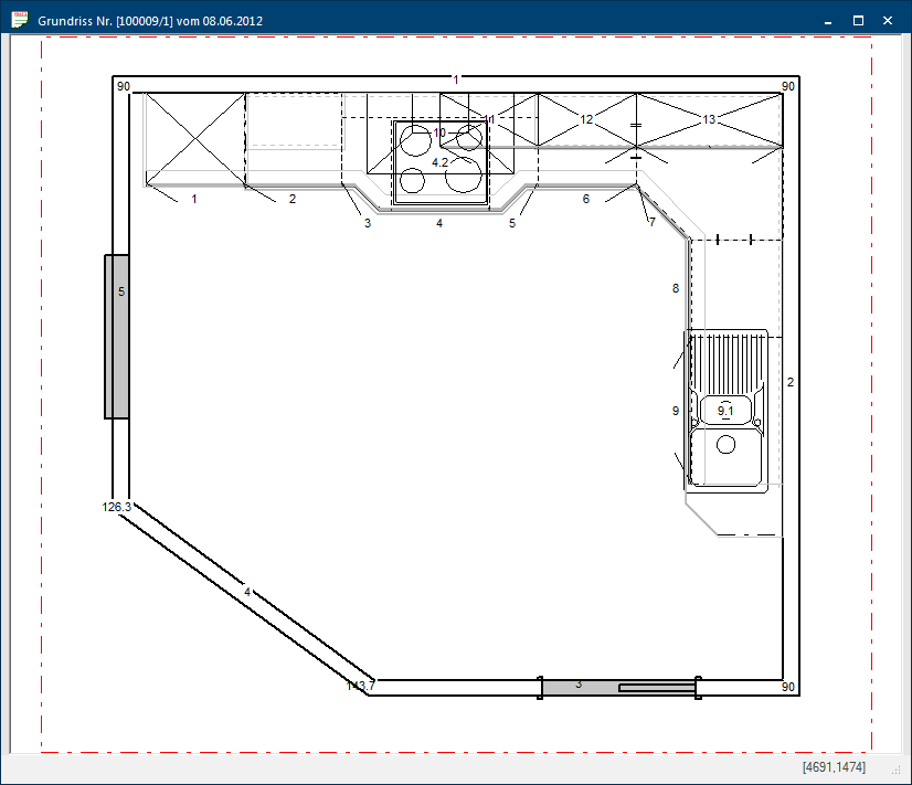
- The following picture displays the floor plan, in which the numbering has been activated, as an example. For all cabinets that are placed on the floor is the position number displayed in front of the article. For cabinets that are hanging at the wall is the position number display in the middle of the article.
Background of numbering transparent
If this option is deactivated, the area behind the numbering will be cleared. Thus, the numbering will not overlap with other graphical elements, like for example other articles or installation symbols. This significantly increases the readability, especially for complex drawings. When desired, the background of the text can however also be set to transparent.
Numbering with frame
A frame is drawn around the numbering, so that you can better distinguish the numbering of the articles from other numbers in the drawing. You can disable the frame if you do not need a frame around the numbering.
With the option Show free dimensions you can define for the selected view if also the dimensions that you have created manually with the function Measure should be displayed. See also: Measure distance
- The following picture shows the floor plan as an example. Because of the activated option Show free dimensions are the manually generated dimensions displayed for the slant as well as for the distance of the worktop to the corner of the room.
You can define if in the selected view also all planned in decoration articles from the neutral catalogue should be displayed via the option Show decoration articles.
- The following picture displays the floor plan, in which the view of decoration articles has been activated, as example.
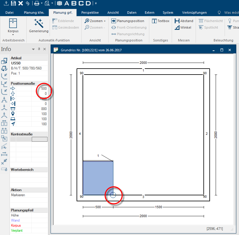
If the option Show reference-point is activated, a marking at the left rear corner of a marked cabinet is displayed. The reference-point is a fixed benchmark that serves for the positioning of the article in the room.
- In the following picture you can recognise the marking of the reference-point as a circle at the left rear corner of the base unit. You can read the absolute position in the room by means of the values in the right column of the table of the two first position measures in the info bar. These values refer to the 0-point of the room, which is always in the lower left of the floor plan. In this example is the 0-point of the room exactly in the lower left wall corner. Hence is the reference-point of the base unit 0 mm from the bottom of the wall and 500 mm from the left wall away.
Installation symbols
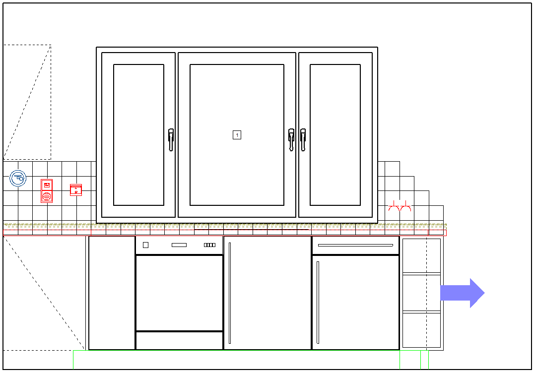
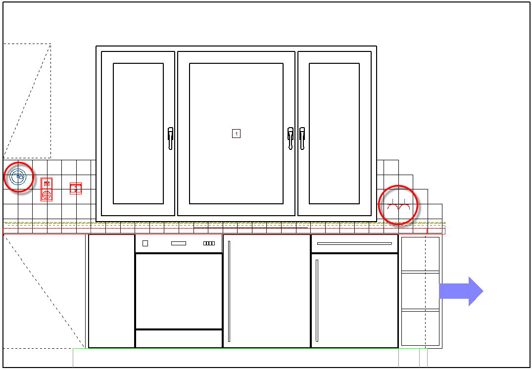
If you have created an installation plan for the floor plan or a wall, you have the possibility to show theses symbols also in the selected view by using the option Installation symbols.
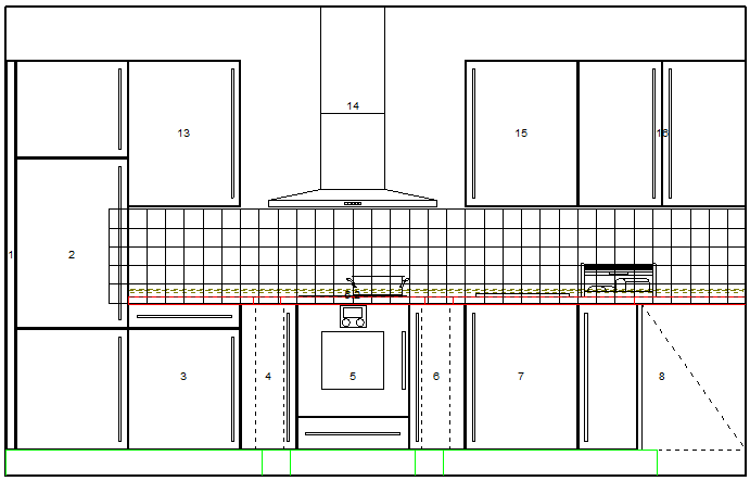
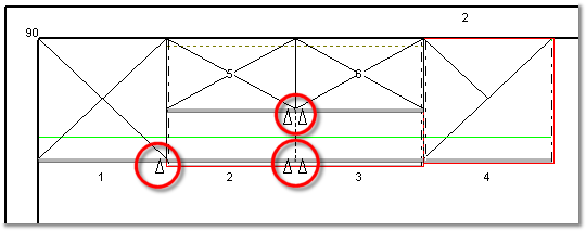
- The following picture shows the front view, in which the view of the installation symbols has been activated, as example. As a result, the installation symbols previously planned via the installation plan can also be displayed here.
Installation symbols background transparent
As you can recognise from the picture above, the background of the installation symbols is in the standard setting cleared, so that you can see the installation symbols always very well. If desired, you can also set the background of the installation symbols to transparent, but this will allow other objects to show through.
You have the possibility to show a graphical element, via which the position of front elements are better visible in the floor plan, by using the option Show cabinet front.
- The following illustration should clarify this. The front is here indicated with a grey line, which has the thickness of an average front. The alignment of a cabinet can be recognised quicker by means of the front display.
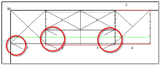
You can arrange how the handing of of doors is displayed in the floor plan via the list box If several options are provides for one function provides, are these often shown in a list. Please click on the little black triangle in the right margin to select the desired option. for the display of the door opening. Both options Design handle and Design handing are for this available.
|
Design handle |
Design handing |
|---|---|
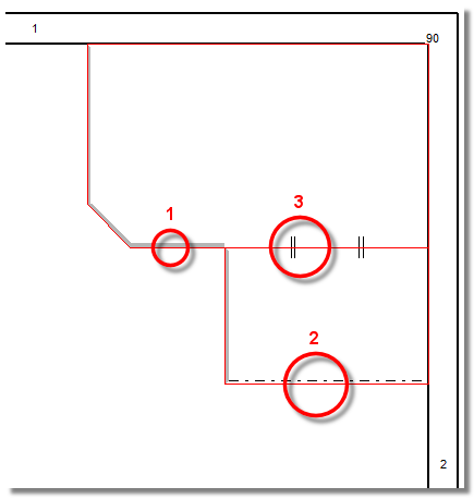
Via the option Show worktop edge status you can show the status of individual worktop edges, if desired. Thereby is the usual red contour line, by which the individual worktops are displayed, supplemented with graphical elements.
- In the following picture you can recognise the three elements of the worktop edge status. The Front edges are marked by a grey line (1). Reductions, sideway edges that usually sustain an edge-glue foil, are marked with a dotted line (2). Butt joints are marked with two short double dashes, that run diagonally on the worktop edge (3).
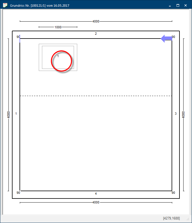
You can activate a red dotted frame for the floor plan as well as the wall view, via the option Show print area. Everything that is displayed within the red dotted frame will later on also be used for the printout. See also: Set Display / Print Area
By using the option Show skylights in all working layers Because the ranges of a design often overlap in the floor plan (e.g. plinth, worktop, carcase etc.) these article groups are classified into working layers. you can arrange if skylights, which are planned in a roof slant, should be visible in all floor plan views and working layers or if they should be hidden for a better overview.
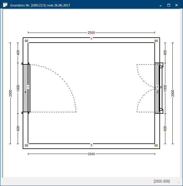
You can specify if in the floor plan the opening range of single or multiple wing windows as well as from doors should be displayed by using the options Show window opening lines and Show door opening lines. This can be useful to be able to assess more precisely the opening range of a window or a door, and therefore to avoid collisions with other articles.
- In the following picture you can recognise the openings line of a door and a double casement window, for example.
